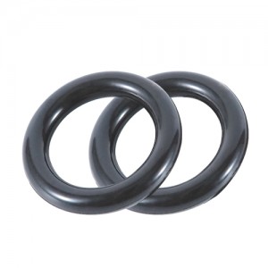
what is the rubber o-ring for and what kind of rubber is used in o-rings ?


what is the rubber o-ring for and what kind of rubber is used in o-rings ?
First -please check the oring size AS568 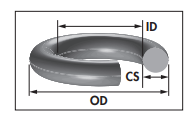
| AS568 SIZE | Nominal ID |
Nominal C/S | Measurements ID in inches | ± ID | Measurements CS in inches | ± CS | Measurements ID in mm | ± ID | Measurements CS in mm | ± C/S | ||||||||||
| -1 | 1/32 | 1/32 | 0.029 | 0.004 | 0.040 | 0.003 | 0.74 | 0.10 | 1.02 | 0.08 | ||||||||||
| -2 | 3/64 | 3/64 | 0.042 | 0.004 | 0.050 | 0.003 | 1.07 | 0.10 | 1.27 | 0.08 | ||||||||||
| -3 | 1/16 | 1/16 | 0.056 | 0.004 | 0.060 | 0.003 | 1.42 | 0.10 | 1.52 | 0.08 | ||||||||||
| -4 | 5/64 | 1/16 | 0.070 | 0.005 | 0.070 | 0.003 | 1.78 | 0.13 | 1.78 | 0.08 | ||||||||||
| -5 | 3/32 | 1/16 | 0.101 | 0.005 | 0.070 | 0.003 | 2.57 | 0.13 | 1.78 | 0.08 | ||||||||||
| -6 | 1/8 | 1/16 | 0.114 | 0.005 | 0.070 | 0.003 | 2.90 | 0.13 | 1.78 | 0.08 | ||||||||||
| -7 | 5/32 | 1/16 | 0.145 | 0.005 | 0.070 | 0.003 | 3.68 | 0.13 | 1.78 | 0.08 | ||||||||||
| -8 | 3/16 | 1/16 | 0.176 | 0.005 | 0.070 | 0.003 | 4.47 | 0.13 | 1.78 | 0.08 | ||||||||||
| -9 | 7/32 | 1/16 | 0.208 | 0.005 | 0.070 | 0.003 | 5.28 | 0.13 | 1.78 | 0.08 | ||||||||||
| -10 | 1/4 | 1/16 | 0.239 | 0.005 | 0.070 | 0.003 | 6.07 | 0.13 | 1.78 | 0.08 | ||||||||||
| -11 | 5/16 | 1/16 | 0.301 | 0.005 | 0.070 | 0.003 | 7.65 | 0.13 | 1.78 | 0.08 | ||||||||||
| -12 | 3/8 | 1/16 | 0.364 | 0.005 | 0.070 | 0.003 | 9.25 | 0.13 | 1.78 | 0.08 | ||||||||||
| -13 | 7/16 | 1/16 | 0.426 | 0.005 | 0.070 | 0.003 | 10.82 | 0.13 | 1.78 | 0.08 | ||||||||||
| -14 | 1/2 | 1/16 | 0.489 | 0.005 | 0.070 | 0.003 | 12.42 | 0.13 | 1.78 | 0.08 | ||||||||||
| -15 | 9/16 | 1/16 | 0.551 | 0.007 | 0.070 | 0.003 | 14.00 | 0.18 | 1.78 | 0.08 | ||||||||||
| -16 | 5/8 | 1/16 | 0.614 | 0.009 | 0.070 | 0.003 | 15.60 | 0.23 | 1.78 | 0.08 | ||||||||||
| -17 | 11/16 | 1/16 | 0.676 | 0.009 | 0.070 | 0.003 | 17.17 | 0.23 | 1.78 | 0.08 | ||||||||||
| -18 | 3/4 | 1/16 | 0.739 | 0.009 | 0.070 | 0.003 | 18.77 | 0.23 | 1.78 | 0.08 | ||||||||||
| -19 | 13/16 | 1/16 | 0.801 | 0.009 | 0.070 | 0.003 | 20.35 | 0.23 | 1.78 | 0.08 | ||||||||||
| -20 | 7/8 | 1/16 | 0.864 | 0.009 | 0.070 | 0.003 | 21.95 | 0.23 | 1.78 | 0.08 | ||||||||||
| -21 | 15/16 | 1/16 | 0.926 | 0.009 | 0.070 | 0.003 | 23.52 | 0.23 | 1.78 | 0.08 | ||||||||||
| -22 | 1 | 1/16 | 0.989 | 0.010 | 0.070 | 0.003 | 25.12 | 0.25 | 1.78 | 0.08 | ||||||||||
| -23 | 1 1/16 | 1/16 | 1.051 | 0.010 | 0.070 | 0.003 | 26.70 | 0.25 | 1.78 | 0.08 | ||||||||||
| -24 | 1 1/8 | 1/16 | 1.114 | 0.010 | 0.070 | 0.003 | 28.30 | 0.25 | 1.78 | 0.08 | ||||||||||
| -25 | 1 3/16 | 1/16 | 1.176 | 0.011 | 0.070 | 0.003 | 29.87 | 0.28 | 1.78 | 0.08 | ||||||||||
| -26 | 1 1/4 | 1/16 | 1.239 | 0.011 | 0.070 | 0.003 | 31.47 | 0.28 | 1.78 | 0.08 | ||||||||||
| -27 | 1 5/16 | 1/16 | 1.301 | 0.011 | 0.070 | 0.003 | 33.05 | 0.28 | 1.78 | 0.08 | ||||||||||
| -28 | 1 3/8 | 1/16 | 1.364 | 0.013 | 0.070 | 0.003 | 34.65 | 0.33 | 1.78 | 0.08 | ||||||||||
| -29 | 1 1/2 | 1/16 | 1.489 | 0.013 | 0.070 | 0.003 | 37.82 | 0.33 | 1.78 | 0.08 | ||||||||||
| -30 | 1 5/8 | 1/16 | 1.614 | 0.013 | 0.070 | 0.003 | 41.00 | 0.33 | 1.78 | 0.08 | ||||||||||
| -31 | 1 3/4 | 1/16 | 1.739 | 0.015 | 0.070 | 0.003 | 44.17 | 0.38 | 1.78 | 0.08 | ||||||||||
| -32 | 1 7/8 | 1/16 | 1.864 | 0.015 | 0.070 | 0.003 | 47.35 | 0.38 | 1.78 | 0.08 | ||||||||||
| -33 | 2 | 1/16 | 1.989 | 0.018 | 0.070 | 0.003 | 50.52 | 0.46 | 1.78 | 0.08 | ||||||||||
| -34 | 2 1/8 | 1/16 | 2.114 | 0.018 | 0.070 | 0.003 | 53.70 | 0.46 | 1.78 | 0.08 | ||||||||||
| -35 | 2 1/4 | 1/16 | 2.239 | 0.018 | 0.070 | 0.003 | 56.87 | 0.46 | 1.78 | 0.08 | ||||||||||
| -36 | 2 3/8 | 1/16 | 2.364 | 0.018 | 0.070 | 0.003 | 60.05 | 0.46 | 1.78 | 0.08 | ||||||||||
| -37 | 2 1/2 | 1/16 | 2.489 | 0.018 | 0.070 | 0.003 | 63.22 | 0.46 | 1.78 | 0.08 | ||||||||||
| -38 | 2 5/8 | 1/16 | 2.614 | 0.020 | 0.070 | 0.003 | 66.40 | 0.51 | 1.78 | 0.08 | ||||||||||
| -39 | 2 3/4 | 1/16 | 2.739 | 0.020 | 0.070 | 0.003 | 69.57 | 0.51 | 1.78 | 0.08 | ||||||||||
| -40 | 2 7/8 | 1/16 | 2.864 | 0.020 | 0.070 | 0.003 | 72.75 | 0.51 | 1.78 | 0.08 | ||||||||||
| -41 | 3 | 1/16 | 2.989 | 0.024 | 0.070 | 0.003 | 75.92 | 0.61 | 1.78 | 0.08 | ||||||||||
| -42 | 3 1/4 | 1/16 | 3.239 | 0.024 | 0.070 | 0.003 | 82.27 | 0.61 | 1.78 | 0.08 | ||||||||||
| -43 | 3 1/2 | 1/16 | 3.489 | 0.024 | 0.070 | 0.003 | 88.62 | 0.61 | 1.78 | 0.08 | ||||||||||
| -44 | 3 3/4 | 1/16 | 3.739 | 0.027 | 0.070 | 0.003 | 94.97 | 0.69 | 1.78 | 0.08 | ||||||||||
| -45 | 4 | 1/16 | 3.989 | 0.027 | 0.070 | 0.003 | 101.32 | 0.69 | 1.78 | 0.08 | ||||||||||
| -46 | 4 1/4 | 1/16 | 4.239 | 0.030 | 0.070 | 0.003 | 107.67 | 0.76 | 1.78 | 0.08 | ||||||||||
| -47 | 4 1/2 | 1/16 | 4.489 | 0.030 | 0.070 | 0.003 | 114.02 | 0.76 | 1.78 | 0.08 | ||||||||||
| -48 | 4 3/4 | 1/16 | 4.739 | 0.030 | 0.070 | 0.003 | 120.37 | 0.76 | 1.78 | 0.08 | ||||||||||
| -49 | 5 | 1/16 | 4.989 | 0.037 | 0.070 | 0.003 | 126.72 | 0.94 | 1.78 | 0.08 | ||||||||||
| -50 | 5 1/4 | 1/16 | 5.239 | 0.037 | 0.070 | 0.003 | 133.07 | 0.94 | 1.78 | 0.08 | ||||||||||
| -102 | 1/16 | 3/32 | 0.049 | 0.005 | 0.103 | 0.003 | 1.24 | 0.13 | 2.62 | 0.08 | ||||||||||
| -103 | 3/32 | 3/32 | 0.081 | 0.005 | 0.103 | 0.003 | 2.06 | 0.13 | 2.62 | 0.08 | ||||||||||
| -104 | 1/8 | 3/32 | 0.112 | 0.005 | 0.103 | 0.003 | 2.84 | 0.13 | 2.62 | 0.08 | ||||||||||
| -105 | 5/32 | 3/32 | 0.143 | 0.005 | 0.103 | 0.003 | 3.63 | 0.13 | 2.62 | 0.08 | ||||||||||
| -106 | 3/16 | 3/32 | 0.174 | 0.005 | 0.103 | 0.003 | 4.42 | 0.13 | 2.62 | 0.08 | ||||||||||
| -107 | 7/32 | 3/32 | 0.206 | 0.005 | 0.103 | 0.003 | 5.23 | 0.13 | 2.62 | 0.08 | ||||||||||
| -108 | 1/4 | 3/32 | 0.237 | 0.005 | 0.103 | 0.003 | 6.02 | 0.13 | 2.62 | 0.08 | ||||||||||
| -109 | 5/16 | 3/32 | 0.299 | 0.005 | 0.103 | 0.003 | 7.59 | 0.13 | 2.62 | 0.08 | ||||||||||
| -110 | 3/8 | 3/32 | 0.362 | 0.005 | 0.103 | 0.003 | 9.19 | 0.13 | 2.62 | 0.08 | ||||||||||
| -111 | 7/16 | 3/32 | 0.424 | 0.005 | 0.103 | 0.003 | 10.77 | 0.13 | 2.62 | 0.08 | ||||||||||
| -112 | 1/2 | 3/32 | 0.487 | 0.005 | 0.103 | 0.003 | 12.37 | 0.13 | 2.62 | 0.08 | ||||||||||
| -113 | 9/16 | 3/32 | 0.549 | 0.007 | 0.103 | 0.003 | 13.94 | 0.18 | 2.62 | 0.08 | ||||||||||
| -114 | 5/8 | 3/32 | 0.612 | 0.009 | 0.103 | 0.003 | 15.54 | 0.23 | 2.62 | 0.08 | ||||||||||
| -115 | 11/16 | 3/32 | 0.674 | 0.009 | 0.103 | 0.003 | 17.12 | 0.23 | 2.62 | 0.08 | ||||||||||
| -116 | 3/4 | 3/32 | 0.737 | 0.009 | 0.103 | 0.003 | 18.72 | 0.23 | 2.62 | 0.08 | ||||||||||
| -117 | 13/16 | 3/32 | 0.799 | 0.010 | 0.103 | 0.003 | 20.29 | 0.25 | 2.62 | 0.08 | ||||||||||
| -118 | 7/8 | 3/32 | 0.862 | 0.010 | 0.103 | 0.003 | 21.89 | 0.25 | 2.62 | 0.08 | ||||||||||
| -119 | 15/16 | 3/32 | 0.924 | 0.010 | 0.103 | 0.003 | 23.47 | 0.25 | 2.62 | 0.08 | ||||||||||
| -120 | 1 | 3/32 | 0.987 | 0.010 | 0.103 | 0.003 | 25.07 | 0.25 | 2.62 | 0.08 | ||||||||||
| -121 | 1 1/16 | 3/32 | 1.049 | 0.010 | 0.103 | 0.003 | 26.64 | 0.25 | 2.62 | 0.08 | ||||||||||
| -122 | 1 1/8 | 3/32 | 1.112 | 0.010 | 0.103 | 0.003 | 28.24 | 0.25 | 2.62 | 0.08 | ||||||||||
| -123 | 1 3/16 | 3/32 | 1.174 | 0.012 | 0.103 | 0.003 | 29.82 | 0.30 | 2.62 | 0.08 | ||||||||||
| -124 | 1 1/4 | 3/32 | 1.237 | 0.012 | 0.103 | 0.003 | 31.42 | 0.30 | 2.62 | 0.08 | ||||||||||
| -125 | 1 5/16 | 3/32 | 1.299 | 0.012 | 0.103 | 0.003 | 32.99 | 0.30 | 2.62 | 0.08 | ||||||||||
| -126 | 1 3/8 | 3/32 | 1.362 | 0.012 | 0.103 | 0.003 | 34.59 | 0.30 | 2.62 | 0.08 | ||||||||||
| -127 | 1 7/16 | 3/32 | 1.424 | 0.012 | 0.103 | 0.003 | 36.17 | 0.30 | 2.62 | 0.08 | ||||||||||
| -128 | 1 1/2 | 3/32 | 1.487 | 0.012 | 0.103 | 0.003 | 37.77 | 0.30 | 2.62 | 0.08 | ||||||||||
| -129 | 1 9/16 | 3/32 | 1.549 | 0.015 | 0.103 | 0.003 | 39.34 | 0.38 | 2.62 | 0.08 | ||||||||||
| -130 | 1 5/8 | 3/32 | 1.612 | 0.015 | 0.103 | 0.003 | 40.94 | 0.38 | 2.62 | 0.08 | ||||||||||
| -131 | 1 11/16 | 3/32 | 1.674 | 0.015 | 0.103 | 0.003 | 42.52 | 0.38 | 2.62 | 0.08 | ||||||||||
| -132 | 1 3/4 | 3/32 | 1.737 | 0.015 | 0.103 | 0.003 | 44.12 | 0.38 | 2.62 | 0.08 | ||||||||||
| -133 | 1 13/16 | 3/32 | 1.799 | 0.015 | 0.103 | 0.003 | 45.69 | 0.38 | 2.62 | 0.08 | ||||||||||
| -134 | 1 7/8 | 3/32 | 1.862 | 0.015 | 0.103 | 0.003 | 47.29 | 0.38 | 2.62 | 0.08 | ||||||||||
| -135 | 1 15/16 | 3/32 | 1.925 | 0.017 | 0.103 | 0.003 | 48.90 | 0.43 | 2.62 | 0.08 | ||||||||||
| -136 | 2 | 3/32 | 1.987 | 0.017 | 0.103 | 0.003 | 50.47 | 0.43 | 2.62 | 0.08 | ||||||||||
| -137 | 2 1/16 | 3/32 | 2.050 | 0.017 | 0.103 | 0.003 | 52.07 | 0.43 | 2.62 | 0.08 | ||||||||||
| -138 | 2 1/8 | 3/32 | 2.112 | 0.017 | 0.103 | 0.003 | 53.64 | 0.43 | 2.62 | 0.08 | ||||||||||
| -139 | 2 3/16 | 3/32 | 2.175 | 0.017 | 0.103 | 0.003 | 55.25 | 0.43 | 2.62 | 0.08 | ||||||||||
| -140 | 2 1/4 | 3/32 | 2.237 | 0.017 | 0.103 | 0.003 | 56.82 | 0.43 | 2.62 | 0.08 | ||||||||||
| -141 | 2 5/16 | 3/32 | 2.300 | 0.020 | 0.103 | 0.003 | 58.42 | 0.51 | 2.62 | 0.08 | ||||||||||
| -142 | 2 3/8 | 3/32 | 2.362 | 0.020 | 0.103 | 0.003 | 59.99 | 0.51 | 2.62 | 0.08 | ||||||||||
| -143 | 2 7/16 | 3/32 | 2.425 | 0.020 | 0.103 | 0.003 | 61.60 | 0.51 | 2.62 | 0.08 | ||||||||||
| -144 | 2 1/2 | 3/32 | 2.487 | 0.020 | 0.103 | 0.003 | 63.17 | 0.51 | 2.62 | 0.08 | ||||||||||
| -145 | 2 9/16 | 3/32 | 2.550 | 0.020 | 0.103 | 0.003 | 64.77 | 0.51 | 2.62 | 0.08 | ||||||||||
| -146 | 2 5/8 | 3/32 | 2.612 | 0.020 | 0.103 | 0.003 | 66.34 | 0.51 | 2.62 | 0.08 | ||||||||||
| -147 | 2 11/16 | 3/32 | 2.675 | 0.022 | 0.103 | 0.003 | 67.95 | 0.56 | 2.62 | 0.08 | ||||||||||
| -148 | 2 3/4 | 3/32 | 2.737 | 0.022 | 0.103 | 0.003 | 69.52 | 0.56 | 2.62 | 0.08 | ||||||||||
| -149 | 2 13/16 | 3/32 | 2.800 | 0.022 | 0.103 | 0.003 | 71.12 | 0.56 | 2.62 | 0.08 | ||||||||||
| -150 | 2 7/8 | 3/32 | 2.862 | 0.022 | 0.103 | 0.003 | 72.69 | 0.56 | 2.62 | 0.08 | ||||||||||
| -151 | 3 | 3/32 | 2.987 | 0.024 | 0.103 | 0.003 | 75.87 | 0.61 | 2.62 | 0.08 | ||||||||||
| -152 | 3 1/4 | 3/32 | 3.237 | 0.024 | 0.103 | 0.003 | 82.22 | 0.61 | 2.62 | 0.08 | ||||||||||
| -153 | 3 1/2 | 3/32 | 3.487 | 0.024 | 0.103 | 0.003 | 88.57 | 0.61 | 2.62 | 0.08 | ||||||||||
| -154 | 3 3/4 | 3/32 | 3.737 | 0.028 | 0.103 | 0.003 | 94.92 | 0.71 | 2.62 | 0.08 | ||||||||||
| -155 | 4 | 3/32 | 3.987 | 0.028 | 0.103 | 0.003 | 101.27 | 0.71 | 2.62 | 0.08 | ||||||||||
| -156 | 4 1/4 | 3/32 | 4.237 | 0.030 | 0.103 | 0.003 | 107.62 | 0.76 | 2.62 | 0.08 | ||||||||||
| -157 | 4 1/2 | 3/32 | 4.487 | 0.030 | 0.103 | 0.003 | 113.97 | 0.76 | 2.62 | 0.08 | ||||||||||
| -158 | 4 3/4 | 3/32 | 4.737 | 0.030 | 0.103 | 0.003 | 120.32 | 0.76 | 2.62 | 0.08 | ||||||||||
| -159 | 5 | 3/32 | 4.987 | 0.035 | 0.103 | 0.003 | 126.67 | 0.89 | 2.62 | 0.08 | ||||||||||
| -160 | 5 1/4 | 3/32 | 5.237 | 0.035 | 0.103 | 0.003 | 133.02 | 0.89 | 2.62 | 0.08 | ||||||||||
| -161 | 5 1/2 | 3/32 | 5.487 | 0.035 | 0.103 | 0.003 | 139.37 | 0.89 | 2.62 | 0.08 | ||||||||||
| -162 | 5 3/4 | 3/32 | 5.737 | 0.035 | 0.103 | 0.003 | 145.72 | 0.89 | 2.62 | 0.08 | ||||||||||
| -163 | 6 | 3/32 | 5.987 | 0.035 | 0.103 | 0.003 | 152.07 | 0.89 | 2.62 | 0.08 | ||||||||||
| -164 | 6 1/4 | 3/32 | 6.237 | 0.040 | 0.103 | 0.003 | 158.42 | 1.02 | 2.62 | 0.08 | ||||||||||
| -165 | 6 1/2 | 3/32 | 6.487 | 0.040 | 0.103 | 0.003 | 164.77 | 1.02 | 2.62 | 0.08 | ||||||||||
| -166 | 6 3/4 | 3/32 | 6.737 | 0.040 | 0.103 | 0.003 | 171.12 | 1.02 | 2.62 | 0.08 | ||||||||||
| -167 | 7 | 3/32 | 6.987 | 0.040 | 0.103 | 0.003 | 177.47 | 1.02 | 2.62 | 0.08 | ||||||||||
| -168 | 7 1/4 | 3/32 | 7.237 | 0.045 | 0.103 | 0.003 | 183.82 | 1.14 | 2.62 | 0.08 | ||||||||||
| -169 | 7 1/2 | 3/32 | 7.487 | 0.045 | 0.103 | 0.003 | 190.17 | 1.14 | 2.62 | 0.08 | ||||||||||
| -170 | 7 3/4 | 3/32 | 7.737 | 0.045 | 0.103 | 0.003 | 196.52 | 1.14 | 2.62 | 0.08 | ||||||||||
| -171 | 8 | 3/32 | 7.987 | 0.045 | 0.103 | 0.003 | 202.87 | 1.14 | 2.62 | 0.08 | ||||||||||
| -172 | 8 1/4 | 3/32 | 8.237 | 0.050 | 0.103 | 0.003 | 209.22 | 1.27 | 2.62 | 0.08 | ||||||||||
| -173 | 8 1/2 | 3/32 | 8.487 | 0.050 | 0.103 | 0.003 | 215.57 | 1.27 | 2.62 | 0.08 | ||||||||||
| -174 | 8 3/4 | 3/32 | 8.737 | 0.050 | 0.103 | 0.003 | 221.92 | 1.27 | 2.62 | 0.08 | ||||||||||
| -175 | 9 | 3/32 | 8.987 | 0.050 | 0.103 | 0.003 | 228.27 | 1.27 | 2.62 | 0.08 | ||||||||||
| -176 | 9 1/4 | 3/32 | 9.237 | 0.055 | 0.103 | 0.003 | 234.62 | 1.40 | 2.62 | 0.08 | ||||||||||
| -177 | 9 1/2 | 3/32 | 9.487 | 0.055 | 0.103 | 0.003 | 240.97 | 1.40 | 2.62 | 0.08 | ||||||||||
| -178 | 9 3/4 | 3/32 | 9.737 | 0.055 | 0.103 | 0.003 | 247.32 | 1.40 | 2.62 | 0.08 | ||||||||||
| -201 | 3/16 | 1/8 | 0.171 | 0.005 | 0.139 | 0.004 | 4.34 | 0.13 | 3.53 | 0.10 | ||||||||||
| -202 | 1/4 | 1/8 | 0.234 | 0.005 | 0.139 | 0.004 | 5.94 | 0.13 | 3.53 | 0.10 | ||||||||||
| -203 | 5/16 | 1/8 | 0.296 | 0.005 | 0.139 | 0.004 | 7.52 | 0.13 | 3.53 | 0.10 | ||||||||||
| -204 | 3/8 | 1/8 | 0.359 | 0.005 | 0.139 | 0.004 | 9.12 | 0.13 | 3.53 | 0.10 | ||||||||||
| -205 | 7/16 | 1/8 | 0.421 | 0.005 | 0.139 | 0.004 | 10.69 | 0.13 | 3.53 | 0.10 | ||||||||||
| -206 | 1/2 | 1/8 | 0.484 | 0.005 | 0.139 | 0.004 | 12.29 | 0.13 | 3.53 | 0.10 | ||||||||||
| -207 | 9/16 | 1/8 | 0.546 | 0.007 | 0.139 | 0.004 | 13.87 | 0.18 | 3.53 | 0.10 | ||||||||||
| -208 | 5/8 | 1/8 | 0.609 | 0.009 | 0.139 | 0.004 | 15.47 | 0.23 | 3.53 | 0.10 | ||||||||||
| -209 | 11/16 | 1/8 | 0.671 | 0.009 | 0.139 | 0.004 | 17.04 | 0.23 | 3.53 | 0.10 | ||||||||||
| -210 | 3/4 | 1/8 | 0.734 | 0.010 | 0.139 | 0.004 | 18.64 | 0.25 | 3.53 | 0.10 | ||||||||||
| -211 | 13/16 | 1/8 | 0.796 | 0.010 | 0.139 | 0.004 | 20.22 | 0.25 | 3.53 | 0.10 | ||||||||||
| -212 | 7/8 | 1/8 | 0.859 | 0.010 | 0.139 | 0.004 | 21.82 | 0.25 | 3.53 | 0.10 | ||||||||||
| -213 | 15/16 | 1/8 | 0.921 | 0.010 | 0.139 | 0.004 | 23.39 | 0.25 | 3.53 | 0.10 | ||||||||||
| -214 | 1 | 1/8 | 0.984 | 0.010 | 0.139 | 0.004 | 24.99 | 0.25 | 3.53 | 0.10 | ||||||||||
| -215 | 1 1/16 | 1/8 | 1.046 | 0.010 | 0.139 | 0.004 | 26.57 | 0.25 | 3.53 | 0.10 | ||||||||||
| -216 | 1 1/8 | 1/8 | 1.109 | 0.012 | 0.139 | 0.004 | 28.17 | 0.30 | 3.53 | 0.10 | ||||||||||
| -217 | 1 3/16 | 1/8 | 1.171 | 0.012 | 0.139 | 0.004 | 29.74 | 0.30 | 3.53 | 0.10 | ||||||||||
| -218 | 1 1/4 | 1/8 | 1.234 | 0.012 | 0.139 | 0.004 | 31.34 | 0.30 | 3.53 | 0.10 | ||||||||||
| -219 | 1 5/16 | 1/8 | 1.296 | 0.012 | 0.139 | 0.004 | 32.92 | 0.30 | 3.53 | 0.10 | ||||||||||
| -220 | 1 3/8 | 1/8 | 1.359 | 0.012 | 0.139 | 0.004 | 34.52 | 0.30 | 3.53 | 0.10 | ||||||||||
| -221 | 1 7/16 | 1/8 | 1.421 | 0.012 | 0.139 | 0.004 | 36.09 | 0.30 | 3.53 | 0.10 | ||||||||||
| -222 | 1 1/2 | 1/8 | 1.484 | 0.015 | 0.139 | 0.004 | 37.69 | 0.38 | 3.53 | 0.10 | ||||||||||
| -223 | 1 5/8 | 1/8 | 1.609 | 0.015 | 0.139 | 0.004 | 40.87 | 0.38 | 3.53 | 0.10 | ||||||||||
| -224 | 1 3/4 | 1/8 | 1.734 | 0.015 | 0.139 | 0.004 | 44.04 | 0.38 | 3.53 | 0.10 | ||||||||||
| -225 | 1 7/8 | 1/8 | 1.859 | 0.018 | 0.139 | 0.004 | 47.22 | 0.46 | 3.53 | 0.10 | ||||||||||
| -226 | 2 | 1/8 | 1.984 | 0.018 | 0.139 | 0.004 | 50.39 | 0.46 | 3.53 | 0.10 | ||||||||||
| -227 | 2 1/8 | 1/8 | 2.109 | 0.018 | 0.139 | 0.004 | 53.57 | 0.46 | 3.53 | 0.10 | ||||||||||
| -228 | 2 1/4 | 1/8 | 2.234 | 0.020 | 0.139 | 0.004 | 56.74 | 0.51 | 3.53 | 0.10 | ||||||||||
| -229 | 2 3/8 | 1/8 | 2.359 | 0.020 | 0.139 | 0.004 | 59.92 | 0.51 | 3.53 | 0.10 | ||||||||||
| -230 | 2 1/2 | 1/8 | 2.484 | 0.020 | 0.139 | 0.004 | 63.09 | 0.51 | 3.53 | 0.10 | ||||||||||
| -231 | 2 5/8 | 1/8 | 2.609 | 0.020 | 0.139 | 0.004 | 66.27 | 0.51 | 3.53 | 0.10 | ||||||||||
| -232 | 2 3/4 | 1/8 | 2.734 | 0.024 | 0.139 | 0.004 | 69.44 | 0.61 | 3.53 | 0.10 | ||||||||||
| -233 | 2 7/8 | 1/8 | 2.859 | 0.024 | 0.139 | 0.004 | 72.62 | 0.61 | 3.53 | 0.10 | ||||||||||
| -234 | 3 | 1/8 | 2.984 | 0.024 | 0.139 | 0.004 | 75.79 | 0.61 | 3.53 | 0.10 | ||||||||||
| -235 | 3 1/8 | 1/8 | 3.109 | 0.024 | 0.139 | 0.004 | 78.97 | 0.61 | 3.53 | 0.10 | ||||||||||
| -236 | 3 1/4 | 1/8 | 3.234 | 0.024 | 0.139 | 0.004 | 82.14 | 0.61 | 3.53 | 0.10 | ||||||||||
| -237 | 3 3/8 | 1/8 | 3.359 | 0.024 | 0.139 | 0.004 | 85.32 | 0.61 | 3.53 | 0.10 | ||||||||||
| -238 | 3 1/2 | 1/8 | 3.484 | 0.024 | 0.139 | 0.004 | 88.49 | 0.61 | 3.53 | 0.10 | ||||||||||
| -239 | 3 5/8 | 1/8 | 3.609 | 0.028 | 0.139 | 0.004 | 91.67 | 0.71 | 3.53 | 0.10 | ||||||||||
| -240 | 3 3/4 | 1/8 | 3.734 | 0.028 | 0.139 | 0.004 | 94.84 | 0.71 | 3.53 | 0.10 | ||||||||||
| -241 | 3 7/8 | 1/8 | 3.859 | 0.028 | 0.139 | 0.004 | 98.02 | 0.71 | 3.53 | 0.10 | ||||||||||
| -242 | 4 | 1/8 | 3.984 | 0.028 | 0.139 | 0.004 | 101.19 | 0.71 | 3.53 | 0.10 | ||||||||||
| -243 | 4 1/8 | 1/8 | 4.109 | 0.028 | 0.139 | 0.004 | 104.37 | 0.71 | 3.53 | 0.10 | ||||||||||
| -244 | 4 1/4 | 1/8 | 4.234 | 0.030 | 0.139 | 0.004 | 107.54 | 0.76 | 3.53 | 0.10 | ||||||||||
| -245 | 4 3/8 | 1/8 | 4.359 | 0.030 | 0.139 | 0.004 | 110.72 | 0.76 | 3.53 | 0.10 | ||||||||||
| -246 | 4 1/2 | 1/8 | 4.484 | 0.030 | 0.139 | 0.004 | 113.89 | 0.76 | 3.53 | 0.10 | ||||||||||
| -247 | 4 5/8 | 1/8 | 4.609 | 0.030 | 0.139 | 0.004 | 117.07 | 0.76 | 3.53 | 0.10 | ||||||||||
| -248 | 4 3/4 | 1/8 | 4.734 | 0.030 | 0.139 | 0.004 | 120.24 | 0.76 | 3.53 | 0.10 | ||||||||||
| -249 | 4 7/8 | 1/8 | 4.859 | 0.035 | 0.139 | 0.004 | 123.42 | 0.89 | 3.53 | 0.10 | ||||||||||
| -250 | 5 | 1/8 | 4.984 | 0.035 | 0.139 | 0.004 | 126.59 | 0.89 | 3.53 | 0.10 | ||||||||||
| -251 | 5 1/8 | 1/8 | 5.109 | 0.035 | 0.139 | 0.004 | 129.77 | 0.89 | 3.53 | 0.10 | ||||||||||
| -252 | 5 1/4 | 1/8 | 5.234 | 0.035 | 0.139 | 0.004 | 132.94 | 0.89 | 3.53 | 0.10 | ||||||||||
| -253 | 5 3/8 | 1/8 | 5.359 | 0.035 | 0.139 | 0.004 | 136.12 | 0.89 | 3.53 | 0.10 | ||||||||||
| -254 | 5 1/2 | 1/8 | 5.484 | 0.035 | 0.139 | 0.004 | 139.29 | 0.89 | 3.53 | 0.10 | ||||||||||
| -255 | 5 5/8 | 1/8 | 5.609 | 0.035 | 0.139 | 0.004 | 142.47 | 0.89 | 3.53 | 0.10 | ||||||||||
| -256 | 5 3/4 | 1/8 | 5.734 | 0.035 | 0.139 | 0.004 | 145.64 | 0.89 | 3.53 | 0.10 | ||||||||||
| -257 | 5 7/8 | 1/8 | 5.859 | 0.035 | 0.139 | 0.004 | 148.82 | 0.89 | 3.53 | 0.10 | ||||||||||
| -258 | 6 | 1/8 | 5.984 | 0.035 | 0.139 | 0.004 | 151.99 | 0.89 | 3.53 | 0.10 | ||||||||||
| -259 | 6 1/4 | 1/8 | 6.234 | 0.040 | 0.139 | 0.004 | 158.34 | 1.02 | 3.53 | 0.10 | ||||||||||
| -260 | 6 1/2 | 1/8 | 6.484 | 0.040 | 0.139 | 0.004 | 164.69 | 1.02 | 3.53 | 0.10 | ||||||||||
| -261 | 6 3/4 | 1/8 | 6.734 | 0.040 | 0.139 | 0.004 | 171.04 | 1.02 | 3.53 | 0.10 | ||||||||||
| -262 | 7 | 1/8 | 6.984 | 0.040 | 0.139 | 0.004 | 177.39 | 1.02 | 3.53 | 0.10 | ||||||||||
| -263 | 7 1/4 | 1/8 | 7.234 | 0.045 | 0.139 | 0.004 | 183.74 | 1.14 | 3.53 | 0.10 | ||||||||||
| -264 | 7 1/2 | 1/8 | 7.484 | 0.045 | 0.139 | 0.004 | 190.09 | 1.14 | 3.53 | 0.10 | ||||||||||
| -265 | 7 3/4 | 1/8 | 7.734 | 0.045 | 0.139 | 0.004 | 196.44 | 1.14 | 3.53 | 0.10 | ||||||||||
| -266 | 8 | 1/8 | 7.984 | 0.045 | 0.139 | 0.004 | 202.79 | 1.14 | 3.53 | 0.10 | ||||||||||
| -267 | 8 1/4 | 1/8 | 8.234 | 0.050 | 0.139 | 0.004 | 209.14 | 1.27 | 3.53 | 0.10 | ||||||||||
| -268 | 8 1/2 | 1/8 | 8.484 | 0.050 | 0.139 | 0.004 | 215.49 | 1.27 | 3.53 | 0.10 | ||||||||||
| -269 | 8 3/4 | 1/8 | 8.734 | 0.050 | 0.139 | 0.004 | 221.84 | 1.27 | 3.53 | 0.10 | ||||||||||
| -270 | 9 | 1/8 | 8.984 | 0.050 | 0.139 | 0.004 | 228.19 | 1.27 | 3.53 | 0.10 | ||||||||||
| -271 | 9 1/4 | 1/8 | 9.234 | 0.055 | 0.139 | 0.004 | 234.54 | 1.40 | 3.53 | 0.10 | ||||||||||
| -272 | 9 1/2 | 1/8 | 9.484 | 0.055 | 0.139 | 0.004 | 240.89 | 1.40 | 3.53 | 0.10 | ||||||||||
| -273 | 9 3/4 | 1/8 | 9.734 | 0.055 | 0.139 | 0.004 | 247.24 | 1.40 | 3.53 | 0.10 | ||||||||||
| -274 | 10 | 1/8 | 9.984 | 0.055 | 0.139 | 0.004 | 253.59 | 1.40 | 3.53 | 0.10 | ||||||||||
| -275 | 10 1/2 | 1/8 | 10.484 | 0.055 | 0.139 | 0.004 | 266.29 | 1.40 | 3.53 | 0.10 | ||||||||||
| -276 | 11 | 1/8 | 10.984 | 0.065 | 0.139 | 0.004 | 278.99 | 1.65 | 3.53 | 0.10 | ||||||||||
| -277 | 11 1/2 | 1/8 | 11.484 | 0.065 | 0.139 | 0.004 | 291.69 | 1.65 | 3.53 | 0.10 | ||||||||||
| -278 | 12 | 1/8 | 11.984 | 0.065 | 0.139 | 0.004 | 304.39 | 1.65 | 3.53 | 0.10 | ||||||||||
| -279 | 13 | 1/8 | 12.984 | 0.065 | 0.139 | 0.004 | 329.79 | 1.65 | 3.53 | 0.10 | ||||||||||
| -280 | 14 | 1/8 | 13.984 | 0.065 | 0.139 | 0.004 | 355.19 | 1.65 | 3.53 | 0.10 | ||||||||||
| -281 | 15 | 1/8 | 14.984 | 0.065 | 0.139 | 0.004 | 380.59 | 1.65 | 3.53 | 0.10 | ||||||||||
| -282 | 16 | 1/8 | 15.955 | 0.075 | 0.139 | 0.004 | 405.26 | 1.91 | 3.53 | 0.10 | ||||||||||
| -283 | 17 | 1/8 | 16.955 | 0.080 | 0.139 | 0.004 | 430.66 | 2.03 | 3.53 | 0.10 | ||||||||||
| -284 | 18 | 1/8 | 17.955 | 0.085 | 0.139 | 0.004 | 456.06 | 2.16 | 3.53 | 0.10 | ||||||||||
| -309 | 7/16 | 3/16 | 0.412 | 0.005 | 0.210 | 0.005 | 10.46 | 0.13 | 5.33 | 0.13 | ||||||||||
| -310 | 1/2 | 3/16 | 0.475 | 0.005 | 0.210 | 0.005 | 12.07 | 0.13 | 5.33 | 0.13 | ||||||||||
| -311 | 9/16 | 3/16 | 0.537 | 0.007 | 0.210 | 0.005 | 13.64 | 0.18 | 5.33 | 0.13 | ||||||||||
| -312 | 5/8 | 3/16 | 0.600 | 0.009 | 0.210 | 0.005 | 15.24 | 0.23 | 5.33 | 0.13 | ||||||||||
| -313 | 11/16 | 3/16 | 0.662 | 0.009 | 0.210 | 0.005 | 16.81 | 0.23 | 5.33 | 0.13 | ||||||||||
| -314 | 3/4 | 3/16 | 0.725 | 0.010 | 0.210 | 0.005 | 18.42 | 0.25 | 5.33 | 0.13 | ||||||||||
| -315 | 13/16 | 3/16 | 0.787 | 0.010 | 0.210 | 0.005 | 19.99 | 0.25 | 5.33 | 0.13 | ||||||||||
| -316 | 7/8 | 3/16 | 0.850 | 0.010 | 0.210 | 0.005 | 21.59 | 0.25 | 5.33 | 0.13 | ||||||||||
| -317 | 15/16 | 3/16 | 0.912 | 0.010 | 0.210 | 0.005 | 23.16 | 0.25 | 5.33 | 0.13 | ||||||||||
| -318 | 1 | 3/16 | 0.975 | 0.010 | 0.210 | 0.005 | 24.77 | 0.25 | 5.33 | 0.13 | ||||||||||
| -319 | 1 1/16 | 3/16 | 1.037 | 0.010 | 0.210 | 0.005 | 26.34 | 0.25 | 5.33 | 0.13 | ||||||||||
| -320 | 1 1/8 | 3/16 | 1.100 | 0.012 | 0.210 | 0.005 | 27.94 | 0.30 | 5.33 | 0.13 | ||||||||||
| -321 | 1 3/16 | 3/16 | 1.162 | 0.012 | 0.210 | 0.005 | 29.51 | 0.30 | 5.33 | 0.13 | ||||||||||
| -322 | 1 1/4 | 3/16 | 1.225 | 0.012 | 0.210 | 0.005 | 31.12 | 0.30 | 5.33 | 0.13 | ||||||||||
| -323 | 1 5/16 | 3/16 | 1.287 | 0.012 | 0.210 | 0.005 | 32.69 | 0.30 | 5.33 | 0.13 | ||||||||||
| -324 | 1 3/8 | 3/16 | 1.350 | 0.012 | 0.210 | 0.005 | 34.29 | 0.30 | 5.33 | 0.13 | ||||||||||
| -325 | 1 1/2 | 3/16 | 1.475 | 0.015 | 0.210 | 0.005 | 37.47 | 0.38 | 5.33 | 0.13 | ||||||||||
| -326 | 1 5/8 | 3/16 | 1.600 | 0.015 | 0.210 | 0.005 | 40.64 | 0.38 | 5.33 | 0.13 | ||||||||||
| -327 | 1 3/4 | 3/16 | 1.725 | 0.015 | 0.210 | 0.005 | 43.82 | 0.38 | 5.33 | 0.13 | ||||||||||
| -328 | 1 7/8 | 3/16 | 1.850 | 0.015 | 0.210 | 0.005 | 46.99 | 0.38 | 5.33 | 0.13 | ||||||||||
| -329 | 2 | 3/16 | 1.975 | 0.018 | 0.210 | 0.005 | 50.17 | 0.46 | 5.33 | 0.13 | ||||||||||
| -330 | 2 1/8 | 3/16 | 2.100 | 0.018 | 0.210 | 0.005 | 53.34 | 0.46 | 5.33 | 0.13 | ||||||||||
| -331 | 2 1/4 | 3/16 | 2.225 | 0.018 | 0.210 | 0.005 | 56.52 | 0.46 | 5.33 | 0.13 | ||||||||||
| -332 | 2 3/8 | 3/16 | 2.350 | 0.018 | 0.210 | 0.005 | 59.69 | 0.46 | 5.33 | 0.13 | ||||||||||
| -333 | 2 1/2 | 3/16 | 2.475 | 0.020 | 0.210 | 0.005 | 62.87 | 0.51 | 5.33 | 0.13 | ||||||||||
| -334 | 2 5/8 | 3/16 | 2.600 | 0.020 | 0.210 | 0.005 | 66.04 | 0.51 | 5.33 | 0.13 | ||||||||||
| -335 | 2 3/4 | 3/16 | 2.725 | 0.020 | 0.210 | 0.005 | 69.22 | 0.51 | 5.33 | 0.13 | ||||||||||
| -336 | 2 7/8 | 3/16 | 2.850 | 0.020 | 0.210 | 0.005 | 72.39 | 0.51 | 5.33 | 0.13 | ||||||||||
| -337 | 3 | 3/16 | 2.975 | 0.024 | 0.210 | 0.005 | 75.57 | 0.61 | 5.33 | 0.13 | ||||||||||
| -338 | 3 1/8 | 3/16 | 3.100 | 0.024 | 0.210 | 0.005 | 78.74 | 0.61 | 5.33 | 0.13 | ||||||||||
| -339 | 3 1/4 | 3/16 | 3.225 | 0.024 | 0.210 | 0.005 | 81.92 | 0.61 | 5.33 | 0.13 | ||||||||||
| -340 | 3 3/8 | 3/16 | 3.350 | 0.024 | 0.210 | 0.005 | 85.09 | 0.61 | 5.33 | 0.13 | ||||||||||
| -341 | 3 1/2 | 3/16 | 3.475 | 0.024 | 0.210 | 0.005 | 88.27 | 0.61 | 5.33 | 0.13 | ||||||||||
| -342 | 3 5/8 | 3/16 | 3.600 | 0.028 | 0.210 | 0.005 | 91.44 | 0.71 | 5.33 | 0.13 | ||||||||||
| -343 | 3 3/4 | 3/16 | 3.725 | 0.028 | 0.210 | 0.005 | 94.62 | 0.71 | 5.33 | 0.13 | ||||||||||
| -344 | 3 7/8 | 3/16 | 3.850 | 0.028 | 0.210 | 0.005 | 97.79 | 0.71 | 5.33 | 0.13 | ||||||||||
| -345 | 4 | 3/16 | 3.975 | 0.028 | 0.210 | 0.005 | 100.97 | 0.71 | 5.33 | 0.13 | ||||||||||
| -346 | 4 1/8 | 3/16 | 4.100 | 0.028 | 0.210 | 0.005 | 104.14 | 0.71 | 5.33 | 0.13 | ||||||||||
| -347 | 4 1/4 | 3/16 | 4.225 | 0.030 | 0.210 | 0.005 | 107.32 | 0.76 | 5.33 | 0.13 | ||||||||||
| -348 | 4 3/8 | 3/16 | 4.350 | 0.030 | 0.210 | 0.005 | 110.49 | 0.76 | 5.33 | 0.13 | ||||||||||
| -349 | 4 1/2 | 3/16 | 4.475 | 0.030 | 0.210 | 0.005 | 113.67 | 0.76 | 5.33 | 0.13 | ||||||||||
| -350 | 4 5/8 | 3/16 | 4.600 | 0.030 | 0.210 | 0.005 | 116.84 | 0.76 | 5.33 | 0.13 | ||||||||||
| -351 | 4 3/4 | 3/16 | 4.725 | 0.030 | 0.210 | 0.005 | 120.02 | 0.76 | 5.33 | 0.13 | ||||||||||
| -352 | 4 7/8 | 3/16 | 4.850 | 0.030 | 0.210 | 0.005 | 123.19 | 0.76 | 5.33 | 0.13 | ||||||||||
| -353 | 5 | 3/16 | 4.975 | 0.037 | 0.210 | 0.005 | 126.37 | 0.94 | 5.33 | 0.13 | ||||||||||
| -354 | 5 1/8 | 3/16 | 5.100 | 0.037 | 0.210 | 0.005 | 129.54 | 0.94 | 5.33 | 0.13 | ||||||||||
| -355 | 5 1/4 | 3/16 | 5.225 | 0.037 | 0.210 | 0.005 | 132.72 | 0.94 | 5.33 | 0.13 | ||||||||||
| -356 | 5 3/8 | 3/16 | 5.350 | 0.037 | 0.210 | 0.005 | 135.89 | 0.94 | 5.33 | 0.13 | ||||||||||
| -357 | 5 1/2 | 3/16 | 5.475 | 0.037 | 0.210 | 0.005 | 139.07 | 0.94 | 5.33 | 0.13 | ||||||||||
| -358 | 5 5/8 | 3/16 | 5.600 | 0.037 | 0.210 | 0.005 | 142.24 | 0.94 | 5.33 | 0.13 | ||||||||||
| -359 | 5 3/4 | 3/16 | 5.725 | 0.037 | 0.210 | 0.005 | 145.42 | 0.94 | 5.33 | 0.13 | ||||||||||
| -360 | 5 7/8 | 3/16 | 5.850 | 0.037 | 0.210 | 0.005 | 148.59 | 0.94 | 5.33 | 0.13 | ||||||||||
| -361 | 6 | 3/16 | 5.975 | 0.037 | 0.210 | 0.005 | 151.77 | 0.94 | 5.33 | 0.13 | ||||||||||
| -362 | 6 1/4 | 3/16 | 6.225 | 0.040 | 0.210 | 0.005 | 158.12 | 1.02 | 5.33 | 0.13 | ||||||||||
| -363 | 6 1/2 | 3/16 | 6.475 | 0.040 | 0.210 | 0.005 | 164.47 | 1.02 | 5.33 | 0.13 | ||||||||||
| -364 | 6 3/4 | 3/16 | 6.725 | 0.040 | 0.210 | 0.005 | 170.82 | 1.02 | 5.33 | 0.13 | ||||||||||
| -365 | 7 | 3/16 | 6.975 | 0.040 | 0.210 | 0.005 | 177.17 | 1.02 | 5.33 | 0.13 | ||||||||||
| -366 | 7 1/4 | 3/16 | 7.225 | 0.045 | 0.210 | 0.005 | 183.52 | 1.14 | 5.33 | 0.13 | ||||||||||
| -367 | 7 1/2 | 3/16 | 7.475 | 0.045 | 0.210 | 0.005 | 189.87 | 1.14 | 5.33 | 0.13 | ||||||||||
| -368 | 7 3/4 | 3/16 | 7.725 | 0.045 | 0.210 | 0.005 | 196.22 | 1.14 | 5.33 | 0.13 | ||||||||||
| -369 | 8 | 3/16 | 7.975 | 0.045 | 0.210 | 0.005 | 202.57 | 1.14 | 5.33 | 0.13 | ||||||||||
| -370 | 8 1/4 | 3/16 | 8.225 | 0.050 | 0.210 | 0.005 | 208.92 | 1.27 | 5.33 | 0.13 | ||||||||||
| -371 | 8 1/2 | 3/16 | 8.475 | 0.050 | 0.210 | 0.005 | 215.27 | 1.27 | 5.33 | 0.13 | ||||||||||
| -372 | 8 3/4 | 3/16 | 8.725 | 0.050 | 0.210 | 0.005 | 221.62 | 1.27 | 5.33 | 0.13 | ||||||||||
| -373 | 9 | 3/16 | 8.975 | 0.050 | 0.210 | 0.005 | 227.97 | 1.27 | 5.33 | 0.13 | ||||||||||
| -374 | 9 1/4 | 3/16 | 9.225 | 0.055 | 0.210 | 0.005 | 234.32 | 1.40 | 5.33 | 0.13 | ||||||||||
| -375 | 9 1/2 | 3/16 | 9.475 | 0.055 | 0.210 | 0.005 | 240.67 | 1.40 | 5.33 | 0.13 | ||||||||||
| -376 | 9 3/4 | 3/16 | 9.725 | 0.055 | 0.210 | 0.005 | 247.02 | 1.40 | 5.33 | 0.13 | ||||||||||
| -377 | 10 | 3/16 | 9.975 | 0.055 | 0.210 | 0.005 | 253.37 | 1.40 | 5.33 | 0.13 | ||||||||||
| -378 | 10 1/2 | 3/16 | 10.475 | 0.060 | 0.210 | 0.005 | 266.07 | 1.52 | 5.33 | 0.13 | ||||||||||
| -379 | 11 | 3/16 | 10.975 | 0.060 | 0.210 | 0.005 | 278.77 | 1.52 | 5.33 | 0.13 | ||||||||||
| -380 | 11 1/2 | 3/16 | 11.475 | 0.065 | 0.210 | 0.005 | 291.47 | 1.65 | 5.33 | 0.13 | ||||||||||
| -381 | 12 | 3/16 | 11.975 | 0.065 | 0.210 | 0.005 | 304.17 | 1.65 | 5.33 | 0.13 | ||||||||||
| -382 | 13 | 3/16 | 12.975 | 0.065 | 0.210 | 0.005 | 329.57 | 1.65 | 5.33 | 0.13 | ||||||||||
| -383 | 14 | 3/16 | 13.975 | 0.070 | 0.210 | 0.005 | 354.97 | 1.78 | 5.33 | 0.13 | ||||||||||
| -384 | 15 | 3/16 | 14.975 | 0.070 | 0.210 | 0.005 | 380.37 | 1.78 | 5.33 | 0.13 | ||||||||||
| -385 | 16 | 3/16 | 15.955 | 0.075 | 0.210 | 0.005 | 405.26 | 1.91 | 5.33 | 0.13 | ||||||||||
| -386 | 17 | 3/16 | 16.955 | 0.080 | 0.210 | 0.005 | 430.66 | 2.03 | 5.33 | 0.13 | ||||||||||
| -387 | 18 | 3/16 | 17.955 | 0.085 | 0.210 | 0.005 | 456.06 | 2.16 | 5.33 | 0.13 | ||||||||||
| -388 | 19 | 3/16 | 18.955 | 0.090 | 0.210 | 0.005 | 481.45 | 2.29 | 5.33 | 0.13 | ||||||||||
| -389 | 20 | 3/16 | 19.955 | 0.095 | 0.210 | 0.005 | 506.85 | 2.41 | 5.33 | 0.13 | ||||||||||
| -390 | 21 | 3/16 | 20.955 | 0.095 | 0.210 | 0.005 | 532.25 | 2.41 | 5.33 | 0.13 | ||||||||||
| -391 | 22 | 3/16 | 21.955 | 0.100 | 0.210 | 0.005 | 557.65 | 2.54 | 5.33 | 0.13 | ||||||||||
| -392 | 23 | 3/16 | 22.940 | 0.105 | 0.210 | 0.005 | 582.68 | 2.67 | 5.33 | 0.13 | ||||||||||
| -393 | 24 | 3/16 | 23.940 | 0.110 | 0.210 | 0.005 | 608.08 | 2.79 | 5.33 | 0.13 | ||||||||||
| -394 | 25 | 3/16 | 24.940 | 0.115 | 0.210 | 0.005 | 633.48 | 2.92 | 5.33 | 0.13 | ||||||||||
| -395 | 26 | 3/16 | 25.940 | 0.120 | 0.210 | 0.005 | 658.88 | 3.05 | 5.33 | 0.13 | ||||||||||
| -425 | 4 1/2 | 1/4 | 4.475 | 0.033 | 0.275 | 0.006 | 113.67 | 0.84 | 6.99 | 0.15 | ||||||||||
| -426 | 4 5/8 | 1/4 | 4.600 | 0.033 | 0.275 | 0.006 | 116.84 | 0.84 | 6.99 | 0.15 | ||||||||||
| -427 | 4 3/4 | 1/4 | 4.725 | 0.033 | 0.275 | 0.006 | 120.02 | 0.84 | 6.99 | 0.15 | ||||||||||
| -428 | 4 7/8 | 1/4 | 4.850 | 0.033 | 0.275 | 0.006 | 123.19 | 0.84 | 6.99 | 0.15 | ||||||||||
| -429 | 5 | 1/4 | 4.975 | 0.037 | 0.275 | 0.006 | 126.37 | 0.94 | 6.99 | 0.15 | ||||||||||
| -430 | 5 1/8 | 1/4 | 5.100 | 0.037 | 0.275 | 0.006 | 129.54 | 0.94 | 6.99 | 0.15 | ||||||||||
| -431 | 5 1/4 | 1/4 | 5.225 | 0.037 | 0.275 | 0.006 | 132.72 | 0.94 | 6.99 | 0.15 | ||||||||||
| -432 | 5 3/8 | 1/4 | 5.350 | 0.037 | 0.275 | 0.006 | 135.89 | 0.94 | 6.99 | 0.15 | ||||||||||
| -433 | 5 1/2 | 1/4 | 5.475 | 0.037 | 0.275 | 0.006 | 139.07 | 0.94 | 6.99 | 0.15 | ||||||||||
| -434 | 5 5/8 | 1/4 | 5.600 | 0.037 | 0.275 | 0.006 | 142.24 | 0.94 | 6.99 | 0.15 | ||||||||||
| -435 | 5 3/4 | 1/4 | 5.725 | 0.037 | 0.275 | 0.006 | 145.42 | 0.94 | 6.99 | 0.15 | ||||||||||
| -436 | 5 7/8 | 1/4 | 5.850 | 0.037 | 0.275 | 0.006 | 148.59 | 0.94 | 6.99 | 0.15 | ||||||||||
| -437 | 6 | 1/4 | 5.975 | 0.037 | 0.275 | 0.006 | 151.77 | 0.94 | 6.99 | 0.15 | ||||||||||
| -438 | 6 1/4 | 1/4 | 6.225 | 0.040 | 0.275 | 0.006 | 158.12 | 1.02 | 6.99 | 0.15 | ||||||||||
| -439 | 6 1/2 | 1/4 | 6.475 | 0.040 | 0.275 | 0.006 | 164.47 | 1.02 | 6.99 | 0.15 | ||||||||||
| -440 | 6 3/4 | 1/4 | 6.725 | 0.040 | 0.275 | 0.006 | 170.82 | 1.02 | 6.99 | 0.15 | ||||||||||
| -441 | 7 | 1/4 | 6.975 | 0.040 | 0.275 | 0.006 | 177.17 | 1.02 | 6.99 | 0.15 | ||||||||||
| -442 | 7 1/4 | 1/4 | 7.225 | 0.045 | 0.275 | 0.006 | 183.52 | 1.14 | 6.99 | 0.15 | ||||||||||
| -443 | 7 1/2 | 1/4 | 7.475 | 0.045 | 0.275 | 0.006 | 189.87 | 1.14 | 6.99 | 0.15 | ||||||||||
| -444 | 7 3/4 | 1/4 | 7.725 | 0.045 | 0.275 | 0.006 | 196.22 | 1.14 | 6.99 | 0.15 | ||||||||||
| -445 | 8 | 1/4 | 7.975 | 0.045 | 0.275 | 0.006 | 202.57 | 1.14 | 6.99 | 0.15 | ||||||||||
| -446 | 8 1/2 | 1/4 | 8.475 | 0.055 | 0.275 | 0.006 | 215.27 | 1.40 | 6.99 | 0.15 | ||||||||||
| -447 | 9 | 1/4 | 8.975 | 0.055 | 0.275 | 0.006 | 227.97 | 1.40 | 6.99 | 0.15 | ||||||||||
| -448 | 9 1/2 | 1/4 | 9.475 | 0.055 | 0.275 | 0.006 | 240.67 | 1.40 | 6.99 | 0.15 | ||||||||||
| -449 | 10 | 1/4 | 9.975 | 0.055 | 0.275 | 0.006 | 253.37 | 1.40 | 6.99 | 0.15 | ||||||||||
| -450 | 10 1/2 | 1/4 | 10.475 | 0.060 | 0.275 | 0.006 | 266.07 | 1.52 | 6.99 | 0.15 | ||||||||||
| -451 | 11 | 1/4 | 10.975 | 0.060 | 0.275 | 0.006 | 278.77 | 1.52 | 6.99 | 0.15 | ||||||||||
| -452 | 11 1/2 | 1/4 | 11.475 | 0.060 | 0.275 | 0.006 | 291.47 | 1.52 | 6.99 | 0.15 | ||||||||||
| -453 | 12 | 1/4 | 11.975 | 0.060 | 0.275 | 0.006 | 304.17 | 1.52 | 6.99 | 0.15 | ||||||||||
| -454 | 12 1/2 | 1/4 | 12.475 | 0.060 | 0.275 | 0.006 | 316.87 | 1.52 | 6.99 | 0.15 | ||||||||||
| -455 | 13 | 1/4 | 12.975 | 0.060 | 0.275 | 0.006 | 329.57 | 1.52 | 6.99 | 0.15 | ||||||||||
| -456 | 13 1/2 | 1/4 | 13.475 | 0.070 | 0.275 | 0.006 | 342.27 | 1.78 | 6.99 | 0.15 | ||||||||||
| -457 | 14 | 1/4 | 13.975 | 0.070 | 0.275 | 0.006 | 354.97 | 1.78 | 6.99 | 0.15 | ||||||||||
| -458 | 14 1/2 | 1/4 | 14.475 | 0.070 | 0.275 | 0.006 | 367.67 | 1.78 | 6.99 | 0.15 | ||||||||||
| -459 | 15 | 1/4 | 14.975 | 0.070 | 0.275 | 0.006 | 380.37 | 1.78 | 6.99 | 0.15 | ||||||||||
| -460 | 15 1/2 | 1/4 | 15.475 | 0.070 | 0.275 | 0.006 | 393.07 | 1.78 | 6.99 | 0.15 | ||||||||||
| -461 | 16 | 1/4 | 15.955 | 0.075 | 0.275 | 0.006 | 405.26 | 1.91 | 6.99 | 0.15 | ||||||||||
| -462 | 16 1/2 | 1/4 | 16.455 | 0.075 | 0.275 | 0.006 | 417.96 | 1.91 | 6.99 | 0.15 | ||||||||||
| -463 | 17 | 1/4 | 16.955 | 0.080 | 0.275 | 0.006 | 430.66 | 2.03 | 6.99 | 0.15 | ||||||||||
| -464 | 17 1/2 | 1/4 | 17.455 | 0.085 | 0.275 | 0.006 | 443.36 | 2.16 | 6.99 | 0.15 | ||||||||||
| -465 | 18 | 1/4 | 17.955 | 0.085 | 0.275 | 0.006 | 456.06 | 2.16 | 6.99 | 0.15 | ||||||||||
| -466 | 18 1/2 | 1/4 | 18.455 | 0.085 | 0.275 | 0.006 | 468.76 | 2.16 | 6.99 | 0.15 | ||||||||||
| -467 | 19 | 1/4 | 18.955 | 0.090 | 0.275 | 0.006 | 481.46 | 2.29 | 6.99 | 0.15 | ||||||||||
| -468 | 19 1/2 | 1/4 | 19.455 | 0.090 | 0.275 | 0.006 | 494.16 | 2.29 | 6.99 | 0.15 | ||||||||||
| -469 | 20 | 1/4 | 19.955 | 0.095 | 0.275 | 0.006 | 506.86 | 2.41 | 6.99 | 0.15 | ||||||||||
| -470 | 21 | 1/4 | 20.955 | 0.095 | 0.275 | 0.006 | 532.26 | 2.41 | 6.99 | 0.15 | ||||||||||
| -471 | 22 | 1/4 | 21.955 | 0.100 | 0.275 | 0.006 | 557.66 | 2.54 | 6.99 | 0.15 | ||||||||||
| -472 | 23 | 1/4 | 22.940 | 0.105 | 0.275 | 0.006 | 582.68 | 2.67 | 6.99 | 0.15 | ||||||||||
| -473 | 24 | 1/4 | 23.940 | 0.110 | 0.275 | 0.006 | 608.08 | 2.79 | 6.99 | 0.15 | ||||||||||
| -474 | 25 | 1/4 | 24.940 | 0.115 | 0.275 | 0.006 | 633.48 | 2.92 | 6.99 | 0.15 | ||||||||||
| -475 | 26 | 1/4 | 25.940 | 0.120 | 0.275 | 0.006 | 658.88 | 3.05 | 6.99 | 0.15 | ||||||||||
| AS568 SIZE | Nominal ID |
Measurements ID in inches | ±ID | Measurements CS in inches | ±CS | Measurements ID in mm | ±ID | Measurements CS in mm | ± C/S | |||||||||||
| -901 | 3/32 | 0.185 | 0.005 | 0.056 | 0.003 | 4.70 | 0.13 | 1.42 | 0.08 | |||||||||||
| -902 | 1/8 | 0.239 | 0.005 | 0.064 | 0.003 | 6.07 | 0.13 | 1.63 | 0.08 | |||||||||||
| -903 | 3/16 | 0.301 | 0.005 | 0.064 | 0.003 | 7.65 | 0.13 | 1.63 | 0.08 | |||||||||||
| -904 | 1/4 | 0.351 | 0.005 | 0.072 | 0.003 | 8.92 | 0.13 | 1.83 | 0.08 | |||||||||||
| -905 | 5/16 | 0.414 | 0.005 | 0.072 | 0.003 | 10.52 | 0.13 | 1.83 | 0.08 | |||||||||||
| -906 | 3/8 | 0.468 | 0.005 | 0.078 | 0.003 | 11.89 | 0.13 | 1.98 | 0.08 | |||||||||||
| -907 | 7/16 | 0.530 | 0.007 | 0.082 | 0.003 | 13.46 | 0.18 | 2.08 | 0.08 | |||||||||||
| -908 | 1/2 | 0.644 | 0.009 | 0.087 | 0.003 | 16.36 | 0.23 | 2.21 | 0.08 | |||||||||||
| -909 | 9/16 | 0.706 | 0.009 | 0.097 | 0.003 | 17.93 | 0.23 | 2.46 | 0.08 | |||||||||||
| -910 | 5/8 | 0.755 | 0.009 | 0.097 | 0.003 | 19.18 | 0.23 | 2.46 | 0.08 | |||||||||||
| -911 | 11/16 | 0.863 | 0.009 | 0.116 | 0.004 | 21.92 | 0.23 | 2.95 | 0.10 | |||||||||||
| -912 | 3/4 | 0.924 | 0.009 | 0.116 | 0.004 | 23.47 | 0.23 | 2.95 | 0.10 | |||||||||||
| -913 | 13/16 | 0.986 | 0.010 | 0.116 | 0.004 | 25.04 | 0.25 | 2.95 | 0.10 | |||||||||||
| -914 | 7/8 | 1.047 | 0.010 | 0.116 | 0.004 | 26.59 | 0.25 | 2.95 | 0.10 | |||||||||||
| -916 | 1 | 1.171 | 0.010 | 0.116 | 0.004 | 29.74 | 0.25 | 2.95 | 0.10 | |||||||||||
| -918 | 1 1/8 | 1.355 | 0.012 | 0.116 | 0.004 | 34.42 | 0.30 | 2.95 | 0.10 | |||||||||||
| -920 | 1 1/4 | 1.475 | 0.014 | 0.118 | 0.004 | 37.47 | 0.36 | 3.00 | 0.10 | |||||||||||
| -924 | 1 1/2 | 1.720 | 0.014 | 0.118 | 0.004 | 43.69 | 0.36 | 3.00 | 0.10 | |||||||||||
| -928 | 1 3/4 | 2.090 | 0.018 | 0.118 | 0.004 | 53.09 | 0.46 | 3.00 | 0.10 | |||||||||||
| -932 | 2 | 2.337 | 0.018 | 0.118 | 0.004 | 59.36 | 0.46 | 3.00 | 0.10 | |||||||||||
Second -Compression rate and stretching amount for orings
The O-ring is a typical extruded seal. The compression ratio and stretching amount of the cross-sectional diameter of the O-ring are the main contents of sealing design, which are of great significance for sealing performance and service life. The good sealing effect of O-ring largely depends on the correct matching of O-ring size and groove size, forming a reasonable compression and stretching amount of the sealing ring.
1. Compression rate
The compression rate W is commonly expressed as follows:
W=(d0 h)/d0 × 100%
In the formula, d0- the cross-sectional diameter of the O-ring in the free state (mm);
H - The distance between the bottom of the O-ring groove and the sealed surface (groove depth), i.e. the cross-sectional height of the O-ring after compression (mm)
2.When selecting the compression ratio of the O-ring, the following three aspects should be considered:
(1). There should be sufficient sealing contact area;(2). Try to minimize the friction force;(3). Try to avoid permanent deformation.
It is not difficult to see from the above factors that there are contradictions between them. A high compression rate can obtain high contact pressure, but an excessive compression rate undoubtedly increases sliding friction and permanent deformation. If the compression rate is too small, it may be due to the coaxiality error and O-ring error of the sealing groove not meeting the requirements, resulting in the disappearance of some compression amount and causing leakage. Therefore, when choosing the compression ratio of the O-ring, it is necessary to weigh various factors. Generally, the compression rate of static seals is greater than that of dynamic seals, but its extreme value should be less than 25%. Otherwise, the compression stress will significantly relax and excessive permanent deformation will occur, especially in high-temperature working conditions.The selection of compression ratio W for O-ring seals should consider the usage conditions, such as static or dynamic seals; Static sealing can be divided into radial sealing and axial sealing; The leakage gap of radial seals (or cylindrical static seals) is the radial gap, while the leakage gap of axial seals (or planar static seals) is the axial gap. Axial sealing is divided into two situations based on whether the pressure medium acts on the inner diameter or outer diameter of the O-ring: internal pressure and external pressure. The increase in internal pressure leads to stretching, while the external pressure reduces the initial stretching of the O-ring. The different forms of static seals mentioned above have different directions of action of the sealing medium on the O-ring, so the pre pressure design is also different. For dynamic seals, it is necessary to distinguish between reciprocating motion seals and rotary motion seals.
(2). Static sealing: Like reciprocating sealing devices, cylindrical static sealing devices generally take W=10% to 15%; The flat static sealing device takes W=15%~30%.For dynamic sealing, it can be divided into three situations; The reciprocating motion is generally taken as W=10% to 15%. When selecting the compression ratio for rotary motion seals, the Joule heat effect must be considered. Generally speaking, the inner diameter of the O-ring used for rotary motion is 3% -5% larger than the shaft diameter, and the compression ratio of the outer diameter is W=3% -8%. For low friction sports, O-rings are generally selected with a smaller compression ratio of W=5% -8% in order to reduce frictional resistance. In addition, the expansion of rubber materials caused by medium and temperature should also be considered. Usually, beyond the given compression deformation, the maximum allowable expansion rate is 15%. Exceeding this range indicates that the material selection is not appropriate, and O-rings of other materials should be used instead, or the given compression deformation rate should be corrected.
(3)Stretching amount ,After being installed in the sealing groove, the O-ring generally has a certain amount of stretching. Like the compression rate, the amount of stretching also has a significant impact on the sealing performance and service life of the O-ring. A large amount of stretching not only makes it difficult to install the O-ring, but also reduces the compression rate due to changes in the cross-sectional diameter d0, leading to leakage. The stretching amount a can be expressed as follows:α= (d+d0)/(d1+d0) In the formula, d - shaft diameter (mm); D1-- Inner diameter of O-ring (mm).The range of stretching amount is 1% -5%. The recommended values for the stretching amount of the O-ring are given in the table. The stretching amount of the O-ring can be selected according to the size of the shaft diameter according to the table's selection limit. Precedence range of compression ratio and stretching amount for O-ring
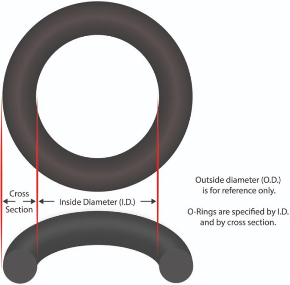
Third-the relationship between the inner diameter(ID), outer diameter(OD), and wire diameter(C/S) of O-ring.
OD=ID+C/S*2 Such as : ID=3MM C/S=1MM OD=3MM+1*2=5MM
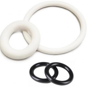
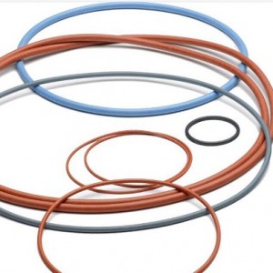
Fourth-Materials commonly used in the production of O-rings
- NBR : NBR O-RING
has excellent oil resistance, benzene resistance, heat resistance, and physical and mechanical properties, and is one of the common raw materials for oil resistant rubber products. It is widely used in the manufacturing of oil resistant gaskets, gaskets, rubber hoses, aircraft mailboxes, flexible packaging, printing and dyeing rubber rollers, cable materials, and adhesives.
- EPDM: EPDM O-RING
with excellent mechanical properties, chemical resistance, and heat resistance, while also exhibiting strong weather resistance. Ethylene propylene diene monomer (EPDM) exhibits excellent properties in terms of ozone resistance, heat resistance, weather resistance, and low softness, making it suitable for applications that are ozone resistant, weather resistant, and UV resistant. However, due to its own structural characteristics, the flame retardancy, oil resistance, and adhesion of EPDM rubber are relatively poor. Nevertheless, this type of rubber has a main chain saturated structure and can be blended with other materials to improve performance by learning from each other's strengths and weaknesses
- VMQ(SILICONE): SILICONE O-RING
with Temperature and oil resistance. Silicone rubber has good low-temperature resistance and can generally work at -55 ℃. After the introduction of phenyl, it can reach -73 ℃. The heat resistance of silicone rubber is also outstanding, and it can work for a long time at 180 ℃. It can withstand several weeks or more of elasticity even at slightly above 200 ℃, and can instantly withstand high temperatures above 300 ℃. Silicone rubber has good breathability and the oxygen permeability is the highest among synthetic polymers. In addition, silicone rubber also has prominent characteristics of physiological inertness and does not cause coagulation, making it widely used in the medical field.
- VITON(FKM FPM):VITON O-RING
has excellent heat resistance, oxidation resistance, oil resistance, corrosion resistance, and atmospheric aging resistance, and has been widely used in fields such as aerospace, aviation, automotive, petroleum, and household appliances. It is a key material that cannot be replaced in the cutting-edge industries of national defense
- HNBR :HNBR O-RING
has good oil resistance (good resistance to fuel oil, lubricating oil, and aromatic solvents); And due to its highly saturated structure, it has good heat resistance, excellent chemical corrosion resistance (good resistance to Freon, acid, and alkali), excellent ozone resistance, and high compression permanent deformation resistance; At the same time, hydrogenated nitrile rubber also has characteristics such as high strength, high tear resistance, and excellent wear resistance, making it one of the most excellent rubbers in terms of comprehensive performance.
- CR(neoprene) : CR O-RING
with good physical and mechanical properties, oil resistance, heat resistance, flame resistance, sunlight resistance, ozone resistance, acid and alkali resistance, and chemical reagent resistance. The disadvantage is poor cold resistance and storage stability. It has high tensile strength, elongation, reversible crystallinity, and good adhesion. Resistant to aging and heat. Excellent oil and chemical resistance
FVMQ: FVMQ O-RING with Good physical and mechanical properties and chemical stability, capable of long-term use at 200 ℃ and short-term use at 250 ℃; The brittleness point ranges from -20 ℃ to -40 ℃; Excellent medium resistance, excellent stability against organic solvents, inorganic acids, and oxidants, especially excellent acid resistance; It has excellent weather resistance and ozone resistance. After being exposed to the atmosphere for several years, its physical and mechanical properties change very little, and its effect on microorganisms is also relatively stable
- FEPM(Aflas):FEPM O-RING
has good stability, chemical resistance, especially resistance to high concentrations of acids, alkalis, and strong oxidizing agents for various types of vehicle fuels, lubricants, brake oils, mineral oils, and silicone oils, as well as excellent resistance to high-pressure water vapor, water, and electrical insulation. It has low breathability and can be used at temperatures between -400 and 200 degrees Celsius
- FFKM :FFKM O-RING
Has elasticity and thermal and chemical stability of polytetrafluoroethylene. Long term working temperature -39~288 degrees Celsius, short-term up to 315 degrees Celsius, still has a certain degree of plasticity below the embrittlement temperature, hard but not brittle, and can be bent. Stable for all chemicals except for swelling in fluorinated solvents. it is the Currently the most expensive rubber in the world.Brand: Kalrez
Fifth- rubber O-ring specifications Measurement methods and tools.
Common measuring tools have :
1-High precision projector

Instrument characteristics :Non contact measurement, making measurement invisible and suitable for measuring thin-walled and soft parts;Has strong image magnification function and stronger small size measurement ability;Fast measurement speed greatly improves measurement efficiency;The high density of sampling points ensures high reliability of measurement;Convenient clamping.
2-Electronic digital caliper

Instrument characteristics :A length measurement tool that uses measurement systems such as capacitive and magnetic grids to display measurement values digitally. The commonly used resolution is 0.01mm, with an allowable error of ± 0.03mm/150mm. There are also high-precision digital calipers with a resolution of 0.005mm, with an allowable error of ± 0.015mm/150mm. There is also a multi-purpose digital display micrometer caliper with a resolution of 0.001mm (which is a national patent for Anyi measuring tools and only they can produce it), with a permissible error of ± 0.005mm/50mm. Due to the intuitive and clear reading, the measurement efficiency is high.
3-π ruler(PITAPE)

Instrument characteristics :
1. The π ruler is composed of an elastic steel strip. Its two ends are respectively engraved with the main and auxiliary rulers. The minimum graduation value of the main ruler is 0.5mm or 1mm; The minimum graduation values of the auxiliary ruler are 0.02mm, 0.05mm, 0.01mm, 0.1mm, etc.
2. When in use, wrap the π ruler around the workpiece and use a vernier reading method to directly read the average diameter of the measured piece.
- Advantages and disadvantages
(1). High accuracy: As the diameter is measured through the circumference of the π ruler, the marking error during the production of the ruler can be reduced by π times and reflected in the measurement results. So in the φ In large diameter measurements above 500mm, its accuracy is higher than that of a vernier caliper. stay φ This advantage is particularly prominent in measurements above 1000mm.
(2). When measuring steel parts with a π ruler, it is not affected by the temperature of the work piece. This is because the π ruler is very thin, and it will be is othermal with the tested piece in a very short period of time during measurement. Additionally, their thermal expansion coefficients are very close, basically overcoming the influence of temperature.
(3. In the measurement of large and extra large diameters, the use of auxiliary components (patented magnetic bridges) allows for easy operation by one person at a time.
(4). Measuring thin-walled parts is not easy to cause deformation of the work piece. (5). Convenient to carry and store (6). The price is low.
(7). Disadvantage: Unable to lock the reading; Geometric deviations such as ovality cannot be measured.
Sixth O-ring Use and o-ring installation.
1. Use of O-ring
O-ring is widely used at the joints of various hydraulic and pneumatic components, cylinder surfaces, and flange surfaces. For O-rings used during movement, when the working pressure is greater than 9.8Mpa and subjected to unidirectional pressure, a retaining ring should be installed on the other side of the O-ring in the direction of pressure; If subjected to bidirectional compression, place a retaining ring on both sides of the O-ring. To reduce friction, wedge-shaped retaining rings can also be used. When the pressure liquid is applied from the left, the right retaining ring is pushed up, and the left retaining ring does not come into contact with the sealed surface, thus reducing the friction force. Overall, the use of retaining rings increases the friction force of the sealing device, and wedge shaped retaining rings are of great significance in reducing this friction force. For fixed O-rings, a retaining ring is also required when the working pressure is greater than 32Mpa.
2. Oring installation
The installation quality of O-rings has a significant impact on their sealing performance and service life. Leakage problems are often caused by poor installation.During the installation process, it is not allowed to have the O-ring scratched, misaligned, or twisted. Before assembly, the sealing groove and sealing mating surface must be strictly cleaned; At the same time, apply lubricating grease to the surface that needs to pass through during the assembly of the O-ring.To prevent the O-ring from being cut or scratched by sharp edges such as sharp corners and threads during installation, a 15 º to 30 º lead-in angle should be left at the shaft end and hole end of the installation. When the O-ring needs to pass through the external thread, a special thin-walled metal guide sleeve should be used to cover the external thread; If the O-ring needs to pass through the orifice, the orifice should be inverted into a corresponding diagonal shape to prevent scratches on the O-ring. The slope angle of the groove is generally a=120 º~140 º
You can learn a lot of related knowledge from here. Later, we will introduce some knowledge about oil seals, hydraulic seal, or other customized rubber parts ,such as Cat oil seal, NBR oil seal ,FKM oil seal, TC oil seal,TB oil seal TA oil seal , SC oil seal SB oil seal ,piston seal ,rod seal ,spring seal ,bonded seal, u cup seal,dust seal,Wiper seal,wear ring ,back up ring , rubber cords, o-ring cords ,so we need more time introduce this knowledge to everyone. Thanks for your time !